
A while back, we took a quick look at how alternating current (AC) signals in our car audio systems work. While the amount of work done by an AC voltage source can be the same as that of a direct current (DC) source, the changes in current flow direction add complications. In this article, we’ll dive a little deeper into AC signals and explain why a fixed-value resistor can’t directly simulate a speaker.
Ohm’s Law – AC and DC Current Flow
Ohm’s law is a constant for both DC and AC circuits. When 1 amp of current flows through a resistor with a value of 1 ohm, then 1 volt of electric potential will be produced across that resistor. If the resistor value is increased to 2 ohms, and we apply 1 volt across it, then 0.5 amp of current flows through it. The triangle below shows the three ways we can calculate voltage, current or resistance if we have two of the other variables.

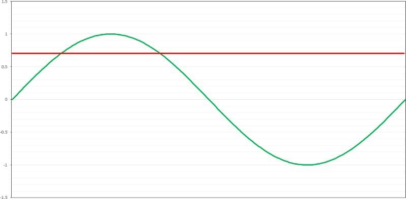
In an AC circuit, we know that the current flow switches back and forth. In home and commercial electrical systems, the voltage is in the shape of a sinusoidal waveform. The work done by the voltage or current is an average level of the signal. For a sine wave, the average level, called the RMS level, is 0.707 times the peak voltage referenced to the ground.
Alternating Current Signals Are Complicated
When current flows through a conductor, it creates a magnetic field around that conductor. This phenomenon is known as Oersted’s law, named for Danish physicist Hans Christian Oersted, who discovered this relationship in April 1820.

In a DC circuit, if we have current flowing through a coil of wire, the magnetic field created in that coil opposes changes in current flow. If we remove the voltage source, the current will continue to flow, even if only for a few milliseconds. This phenomenon is why many automotive relays have a diode on the bottom of a socket. The diode shunts the reverse-polarity current spike that results when we remove the voltage source. As a result, the magnetic field in the relay coil collapses and produces a voltage spike. This spike can damage the circuitry driving the relay or cause arcing in a switch.

Audio Signals Are Complicated
The current flowing to a speaker (or more specifically, a tweeter) may change direction as often as 20,000 times a second. All speakers (that we will worry about) use a voice coil that creates a magnetic field that makes the cone move. This same magnetic field opposes changes to the current flow direction. As such, we have more opposition to AC flow than we would for the same amount of DC current.
If we connect a digital multimeter to a speaker, the meter applies a tiny DC current to the voice coil. The number on the meter screen tells us the DC resistance in voice coil winding.
For AC circuits, we need to measure impedance. The Oxford Dictionary defines impedance as “the effective resistance of an electric circuit or component to alternating current, arising from the combined effects of ohmic resistance and reactance.” Since we skipped over it, reactance is the opposition to AC current flow caused by inductance or capacitance. For example, the voice coil in a speaker will act as an inductor at mid to high frequencies.
Let’s look at a sizeable 6.5-inch woofer. If I use a high-quality digital multimeter to measure the resistance, we get a reading of 3.7 ohms.

If I want to know how the speaker opposes the flow of AC current, I need to feed it an AC signal and measure the opposition to current flow at any frequency relevant to the application for the driver. For this article, I’ll use the Smith & Larson Woofer Tester 2. This device can measure DC resistance and inductive and reactive capacitance at any frequency up to 20 kHz. The result is a plot of impedance (AC opposite to current flow) along with a phase plot that tells us whether the load is capacitive or inductive.

If we look closely at the impedance measurement, we can see that the woofer has an impedance of about 30 ohms at a frequency of 42 Hz. This is the driver’s resonant frequency (Fs) and represents the point at which the least amount of current produces the most output.
At higher frequencies, the inductance of the voice coil becomes the primary opposition to AC current flow in the speaker. The Woofer Tester 2 measured the inductance of this driver as having a value of 0.827 millihenry. You can see that the impedance starts to rise at an exponential rate above about 250 Hz. By the time the drive frequency is at 20 kHz, the impedance is approximately 54 ohms.
Driving a woofer or subwoofer is one type of challenge for an amplifier. This task requires significant amounts of power. The load can also be heavily reactive, meaning current and voltage may not be in phase with each other.
Driving a set of component speakers is an entirely different scenario. Even the most minute changes in output level can be readily apparent to the listener. Since speakers can present significantly varying impedances based on frequency, the voltage and current supplied by the amplifier will change as well. These variances in load impedance can result in small changes in output level as the amplifier’s circuitry interacts with the load to create a voltage divider. In systems where there is no equalization, especially in home audio systems, these variances can change how the listener perceives the music.


We created this complex reactive load to challenge amplifiers that cross the BestCarAudio.com test bench. We take frequency response measurements into all the rated loads for the amp and a measurement when connected to this simulated reactive load. Better amplifiers exhibit smaller changes in output level relative to changes in load impedance.

The graph above shows the effective frequency response of an amplifier when fed a 4-ohm resistor (in red) and 2-ohm resistor (violet) and our reactive test load (in black). As you can see, the output of the amp varies depending on what it’s connected to. This phenomenon is more common with Class-D amplifiers than with Class-AB designs.
Why Is Impedance Important to Car Audio Systems?
There are a few takeaways from this article. First, if you measure the resistance of a speaker with a multimeter, you are getting a general feel for its ability to pass current. For example, if the meter measures 3.7 to 4.2 ohms, then you have a nominally 4-ohm speaker.
However, if you intend to design passive crossovers, you need to know the exact impedance around the crossover frequency to choose the correct values. While very few people create passive crossovers these days, we do see many people suggesting that those circuits are interchangeable between different brands, makes and models of speakers. Nothing could be further from the truth. You can’t assume a crossover designed for Brand A speakers will function adequately or sound right with Brand B.
Another consideration about AC signals surfaces when measuring power in a reactive load (like a speaker). The opposition to changes in current means that current peaks lag behind voltage peaks in inductive loads. If you want to measure power from an amplifier when connected to a speaker, you need to measure current and voltage simultaneously. We don’t mean by using a voltmeter and current clamp and taking peak readings. You need to measure both using something like the D’Amore Engineering AMM-1. Those “clamped” power readings the SPL guys talk about are meaningless.
This article is written and produced by the team at www.BestCarAudio.com. Reproduction or use of any kind is prohibited without the express written permission of 1sixty8 media.
